Cesar Steve
Suclupe Martinez
Senior Multidisciplinary Designer · Civil, Piping & BIM Automation

Profile
Multidisciplinary designer with ~18 years of experience in civil, mechanical and piping engineering, specialized in BIM-based design and modelling of
road infrastructure, mining platforms and industrial plants. I have worked directly with Peruvian road standards (DG-2014, DG-2018) and international codes such as
ASME B31.3 for process piping and ASTM A36 for steel structures, ensuring that every solution is technically consistent and fully traceable against the applicable standards.
In road engineering, I have developed geometric design of highways (plan, profile, cross-sections), drainage, hydraulic structures, detours and associated structures (bridges, culverts, box culverts), including BIM modelling and construction-sequence simulations for large transportation and mining projects. In piping, I have modelled and documented process systems, city gates, tanks and associated networks under ASME B31.3 criteria. In steel structures, I have been involved in the modelling and quantity take-off of pipe racks, platforms, industrial buildings and port/marine elements.
In parallel to project work, I have 6+ years of experience developing engineering automation solutions using C#/.NET, FastAPI and Python, as well as Windows Forms user interfaces acting as the frontend for internal tools. I have built plugins and services that integrate with Autodesk Civil 3D, Plant 3D and AutoCAD, including APIs for standards queries and automatic generation of design parameters. This combination of project experience and software development allows me to quickly identify critical pain points (quantities, reports, setting-out, multidisciplinary coordination) and turn them into concrete tools that reduce time, errors and rework.
Available for international remote contracts — freelance, part-time or full-time. Flexible across GMT (UK), AEST (Australia) and EST/PST (North America) time zones.
Selected case studies
From DG-2018 automation to large waste dumps, dams and Plant 3D pipelines.
Case Study 1
DG-2018 Road Design Automation
Case Study 2
Las Bambas – Botadero Pionero (~146 Mm³)
Case Study 3
Chonta Dam – Road & Instrumentation
Case Study 4
Multi-mine Civil & Piping Package
Case Study 5
Plant 3D Admin & Isometric Automation
Case Study 6
Teaching Autodesk Plant 3D / P&ID
Case Study 7
Stockpile System CSA – Fluor / Chinalco
Case Study 8
I-405 As-Built ADL – Protecnium / OHLA USA
Case Study 1
DG-2018 Road Design Automation – CUMBRA
Project
DG-2018 Road Design Automation for Civil 3D
Client / Company
CUMBRA Ingeniería – Internal tool used across mining and road projects
Location / Sector
Peru – Mining access roads and infrastructure
Role
Lead Developer & Senior Civil 3D Designer
Tech & Tools
Autodesk Civil 3D, AutoCAD, C#/.NET, Python, FastAPI, REST APIs, Excel
Challenge
Road alignments for mining projects were being designed in Civil 3D but checked manually in Excel using DG-2018 highway design criteria. This process was slow, error-prone and difficult to standardize across projects and designers. Curve element tables were also generated semi-manually, increasing the risk of inconsistencies between the model, spreadsheets and issued drawings.
What I did
- Designed and implemented a Python + FastAPI backend that encodes the main DG-2018 geometric design rules for road alignments (minimum radii, tangent lengths, speeds, etc.).
- Developed a C#/.NET plugin for Civil 3D that reads alignment geometry directly from the model (tangents, curves, spirals, PIs) and sends it to the DG-2018 API for validation.
- Automated the generation of curve element tables inside Civil 3D, including stations, radii, deflection angles and other data required for staking and verification.
- Implemented a Windows Forms front-end so designers can select alignments, run DG-2018 checks and export standardized reports without leaving the CAD environment.
- Structured the solution so that it can be extended to support additional standards and reused across multiple projects.
Impact
- Reduced road alignment verification time from hours of manual spreadsheet work to a few minutes directly in Civil 3D.
- Eliminated repeated manual transcription between the model and Excel, decreasing the risk of human error in curve parameters and stationing.
- Standardized curve element tables and DG-2018 compliance checks across different designers and projects.
- Created a reusable framework that CUMBRA can leverage for other rule-based design checks, improving overall quality and consistency.
Case Study 2
Las Bambas – “Botadero Pionero” (~146 Mm³) – CUMBRA
Project
Las Bambas – “Botadero Pionero” (~146 million m³) and associated earthworks
Client / Company
CUMBRA Ingeniería
Location / Sector
Peru – Large-scale open pit mining
Role
Senior Multidisciplinary Designer (Civil / Earthworks / BIM)
Tech & Tools
Autodesk Civil 3D, AutoCAD, Navisworks Manage, Google Earth, Excel
Challenge
The “Botadero Pionero” waste dump required the management of extremely large volumes of material (~146 million m³), with strict constraints on stability, drainage and operational access. The project also included platforms, haul roads, drainage and sub-drainage systems that needed to be fully coordinated with existing and future mine infrastructure. Documentation had to be consistent and clear for both design review and construction teams.
What I did
- Developed detailed earthwork models in Civil 3D for the Botadero Pionero, including grading, platforms, slopes and access roads.
- Generated and maintained corridor models, cross-sections and volume reports to support design decisions and monthly progress evaluations.
- Designed drainage and sub-drainage solutions (ditches, culverts, box culverts and channels) integrated with waste dump geometry and surrounding terrain.
- Prepared full drawing packages: plan & profile sheets, cross-sections, grading plans and earthwork summaries for construction and internal QA.
- Used Navisworks to coordinate civil models with structural and piping elements, identifying potential clashes at early stages.
- Exported KMZ files and used Google Earth for high-level review of dump footprint, haul roads and interfaces with existing mine layout.
Impact
- Provided a reliable 3D basis for decision-making on one of the largest waste dumps in the operation.
- Improved alignment between design intent, volumes calculations and construction quantities.
- Reduced design iterations by identifying conflicts between earthworks, drainage and other disciplines early in the process.
- Supported project reporting and management with clear, traceable geometry and volume data.
Case Study 3
Chonta Dam – Road Access & Instrumentation – AFRY
Project
Reformulation of the technical dossier for “Regulación de las Aguas del Río Chonta mediante la Presa Chonta”
Client / Company
AFRY (consulting engineer)
Location / Sector
Cajamarca, Peru – Hydropower / water resources / dam engineering
Role
Multidisciplinary Designer – Road Design, Geotechnical Profiles and Instrumentation Layout
Tech & Tools
Autodesk Civil 3D, AutoCAD, Excel, Google Earth
Challenge
The Chonta dam project required a new or improved road connection (tertiary class with tunnel) and a consistent set of civil and geotechnical drawings to support dam design, construction planning and risk analysis. Information had to be coordinated between road design, geology, geotechnics, structures and hydraulic design, while keeping drawings readable and aligned with Peruvian standards.
What I did
- Developed the geometric design of the access/variant road in Civil 3D, including horizontal and vertical alignments, cross-sections and basic earthworks.
- Produced plan & profile sheets, typical and special sections for the road, considering constraints from topography, geology and dam facilities.
- Prepared geological and geotechnical profiles, integrating data from investigations into clear drawings usable by geotechnical and structural teams.
- Worked on layouts for dam instrumentation: location of instruments, galleries and access points for readings, ensuring logical routes and clarity for operation teams.
- Supported the preparation of general arrangement drawings for the dam area, including access roads, ancillary facilities, spoil areas and quarries.
Impact
- Delivered a coherent geometric road design integrated with dam and geotechnical requirements.
- Improved coordination between civil, geotechnical and structural disciplines by providing consistent profiles and sections.
- Clarified the location and arrangement of instrumentation, facilitating long-term monitoring and operations.
- Contributed to a more robust and buildable technical dossier for authorities and the client.
Case Study 4
Multi-mine Civil, Structures & Piping Package – WORLEY
Project
Civil and piping design for multiple mining projects (Mina Justa, Escondida, Los Pelambres, Nexa, Minsur, Antamina, Las Bambas, Yanacocha)
Client / Company
WORLEY Ingeniería Perú S.A.
Location / Sector
Peru & Chile – Mining (copper, polymetallic)
Role
Senior Multidisciplinary Designer (Civil / Piping / Structures)
Tech & Tools
Autodesk Civil 3D, AutoCAD, Plant 3D, Navisworks Manage, Advance Steel, Revit, Excel
Challenge
Different mining projects required consistent, high-quality civil and piping deliverables under tight schedules and various client standards. Scope ranged from earthworks and platforms to pipelines, foundations, electrical rooms and pipe racks. Coordinating models and drawings between disciplines and locations (Peru, Chile, Australia teams) was essential to avoid rework during construction.
What I did
- For Mina Justa, acted as lead for earthworks: platforms, access roads, cut/fill models and volume reports in Civil 3D, supporting both design and cost teams.
- For projects such as BHP Escondida and Los Pelambres (Chile), developed civil layouts, excavations and foundations for electrical rooms, transformer pads and duct banks.
- At Nexa (Cajamarquilla) and Minsur (San Germán), designed and modified steel pipe racks, platforms and access walkways, coordinating foundations and steelwork with piping constraints.
- Produced plan views, profiles, cross-sections and detailed drawings for civil works, as well as piping layouts and support details in AutoCAD / Plant 3D.
- Used Navisworks for multidisciplinary coordination (civil, piping, structures, equipment), supporting clash detection and model review sessions.
- Created and maintained Excel-based summaries, quantities and reports for internal checking and client submissions, sometimes fed by Civil 3D outputs or custom scripts.
Impact
- Provided consistent deliverables across a diverse portfolio of mining projects, helping Worley maintain quality and meet client expectations.
- Reduced field clashes and design changes by solving many conflicts at model stage with Navisworks.
- Supported planning and cost control through reliable volumes and quantities derived from Civil 3D models.
- Helped integrate civil, structural and piping design across teams in Peru, Chile and other locations.
Case Study 5
Plant 3D Admin & Isometric Automation – Procure SpA
Project
Autodesk Plant 3D environment administration and isometric automation for mining projects
Client / Company
Servicios Procure SpA (Chile) – remote support
Location / Sector
Chile – Mining / industrial plants
Role
Plant 3D Administrator & CAD/BIM Automation Developer
Tech & Tools
Autodesk Plant 3D, AutoCAD P&ID, C#/.NET, Windows Forms, Excel, Navisworks
Challenge
The client managed several Plant 3D-based projects with different teams and standards. Manual configuration of specs, isometric styles and data consistency checks consumed a lot of time and often led to discrepancies in line data, tags and isometric drawings. They needed a more controlled Plant 3D environment and automation to generate and validate isometrics at scale.
What I did
- Acted as Plant 3D administrator, organizing projects, specs, catalogs and isometric styles to create a coherent and maintainable environment.
- Standardized naming conventions and basic project templates to reduce setup time and inconsistencies between projects.
- Developed C#/.NET utilities with Windows Forms front-ends to:
- Automate batch generation and update of isometric drawings from Plant 3D models.
- Validate line data, tags and key properties before issuing drawings.
- Worked closely with designers and project leads to align the tools with their day-to-day workflows and adjust logic based on feedback.
Impact
- Reduced manual effort in generating and updating isometric drawings, freeing designers to focus on actual design work.
- Improved consistency of tags, line properties and isometric outputs across projects.
- Gave the client a more robust and predictable Plant 3D environment that can be reused in future projects.
- Demonstrated the value of combining Plant 3D expertise with .NET development to solve recurring CAD problems.
Case Study 6
Teaching Autodesk Plant 3D / P&ID – SEMCO CAD
Project
30-hour Autodesk Plant Design Suite training (Plant 3D & AutoCAD P&ID)
Client / Company
SEMCO CAD – Training & CAD Solutions
Location / Sector
Peru – Education / industrial plants
Role
Course Instructor – Autodesk Plant 3D & AutoCAD P&ID
Tech & Tools
Autodesk Plant 3D, AutoCAD P&ID, Navisworks, AutoCAD, real project examples
Challenge
Many technicians and engineers in industrial plant projects needed practical skills in Plant 3D and P&ID, beyond basic commands. The goal was to train them to build usable 3D models, P&IDs, specs and isometrics aligned with real project workflows, not just academic exercises.
What I did
- Designed and delivered a 30-hour course focused on real-world use of AutoCAD Plant 3D and AutoCAD P&ID, with a small introduction to Navisworks.
- Covered P&ID creation, 3D piping modeling, equipment, supports, specs, catalogs, isometric generation and basic reporting.
- Structured the course around a simplified but realistic plant model, so students could understand the full workflow from P&ID to 3D to isometrics and reports.
- Included practical tips from mining and industrial projects (Las Bambas, refineries, gas stations) to connect the software training with field reality.
Impact
- Helped multiple generations of designers and engineers become productive in Plant 3D / P&ID in a short time.
- Strengthened the local ecosystem of Plant 3D users, which indirectly supports companies adopting BIM for industrial plants.
- Reinforced my own expertise by constantly explaining and refining best practices, benefiting my project work as well.
Case Study 7
Stockpile System CSA – Fluor / Chinalco MMG Copper
Project
Stockpile System — civil, structural and architectural 3D modeling for Chinalco copper mining operation
Client / Company
Fluor Corporation — Minera Chinalco Peru S.A. / MMG
Location / Sector
Peru — Large-scale copper mining
Role
Senior CSA Designer — SmartPlant 3D
Tech & Tools
SmartPlant 3D (SP3D), Civil 3D, MicroStation, AutoCAD
Challenge
The project required complete 3D modeling of the stockpile system for Chinalco's copper mining operation under the CSA (Civil, Structural & Architecture) area. The system includes the ore storage cone formed by material discharged from the conveyor belt, the underground reclaim tunnel with draw points where material drops by gravity onto the lower conveyor belt, and all the concrete and steel infrastructure supporting the system. Coordination with the mechanical discipline team in Chile via MicroStation was critical for federated model compatibility.
What I did
- Modeled reinforced concrete structures in SmartPlant 3D (SP3D): reclaim tunnel, slabs, walls, foundations and retaining elements for the stockpile system.
- Modeled steel structures in SP3D: steel framing, access platforms, beams, supports and auxiliary elements of the stacking system.
- Developed earthworks and civil access associated with the stockpile in Civil 3D: platforms, cut/fill, profiles and cross-sections.
- Coordinated with the mechanical discipline team in Chile via MicroStation for interdisciplinary 3D model compatibility.
- Reviewed interferences between CSA, mechanical and equipment disciplines in the federated model.
- Prepared technical documentation: layout drawings, sections and concrete and steel details for engineering issuance.
Impact
- Complete and coordinated 3D CSA model of the stockpile system in one of Peru's most relevant copper projects (Chinalco / MMG).
- Effective compatibility between CSA (Peru) and mechanical (Chile) disciplines through a federated model in SP3D and MicroStation.
- Technical documentation of concrete and steel structures ready for engineering and construction issuance.
- Active SP3D experience for Tier-1 EPC projects under Fluor Corporation — a global reference EPC company.
Case Study 8
I-405 As-Built ADL – Protecnium USA / OHLA USA
Project
I-405 Improvement Project — As-Built documentation for ADL-impacted intersections, California
Client / Company
Protecnium USA / OHLA USA — I-405 Improvement Project, California, USA
Location / Sector
California, USA — Highway infrastructure
Role
Senior Multidisciplinary BIM Designer — Remote
Tech & Tools
Civil 3D, OpenRoads Designer, MicroStation, AutoCAD, custom Python scripts
Challenge
The project required production of As-Built deliverables for the I-405 segment between stations 704+000 and 1114+000, focusing on 12 intersection zones where ADL (Aerially Deposited Lead) was identified — contaminated material requiring rigorous technical documentation under specific California project protocols. The key technical challenge was vectorization and cross-referencing of existing topography, the original design, and new client requirements — a high volume of data that had to be accurately reconciled before plan production could begin. Deliverables had to be generated in parallel in Civil 3D (Autodesk workflow) and OpenRoads Designer (Bentley workflow) per OHLA USA team requirements.
What I did
- Prepared and updated As-Built plan and profile drawings for the 12 intersection zones — ~36 sheets total (~3 sheets per zone).
- Developed and adjusted alignments, longitudinal profiles and cross-sections in Civil 3D and OpenRoads Designer.
- Processed existing topographic information and cross-referenced it with the original project to accurately represent as-executed field conditions.
- Developed a custom Python script to automate vectorization and cross-referencing between existing data and the original design, significantly reducing manual processing time.
- Generated specific graphic documentation for ADL — Aerially Deposited Lead — zones in compliance with project protocols.
- Coordinated directly with the OHLA USA chief surveyor to ensure consistency between existing drawings, topographic data and final deliverables.
- Produced deliverables compatible with the client's Autodesk (Civil 3D) and Bentley (OpenRoads Designer / MicroStation) workflows.
Impact
- ~36 As-Built plan sheets produced for 12 intersections in ADL zones under California highway technical standards.
- Automation of the vectorization process via a custom Python script — significant reduction of manual processing time on high-volume data.
- Dual-ecosystem deliverables compatible with both Autodesk and Bentley client workflows.
- First highway infrastructure project in the United States — successful adaptation to international standards, effective remote coordination with a North American engineering team, and management of ADL protocols under California regulations.
- Demonstrated full-delivery remote work capacity for a USA client.
Visual Samples
Selected Drawings & Models
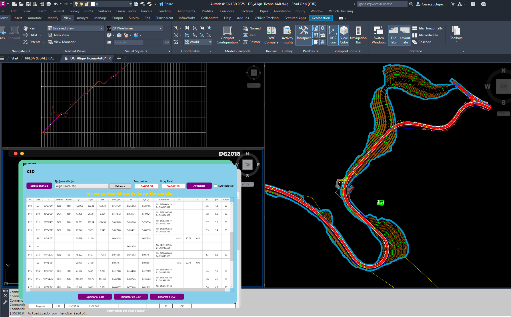
Civil 3D – Road plan & profile with DG-2018 tables
Huacho–Pativilca or Chonta access road – geometric design & replanteo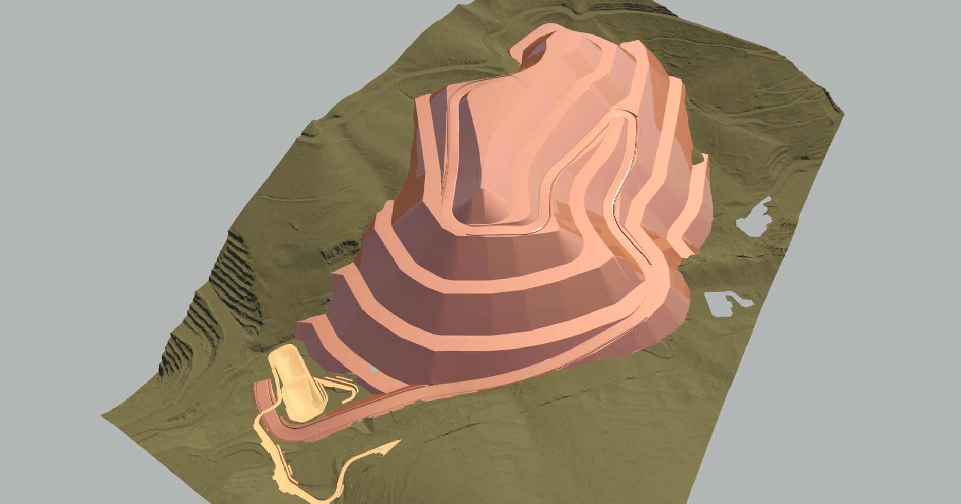
Earthworks – Botadero Pionero 3D model
Platforms, slopes, drainage and haul roads – Las Bambas (CUMBRA)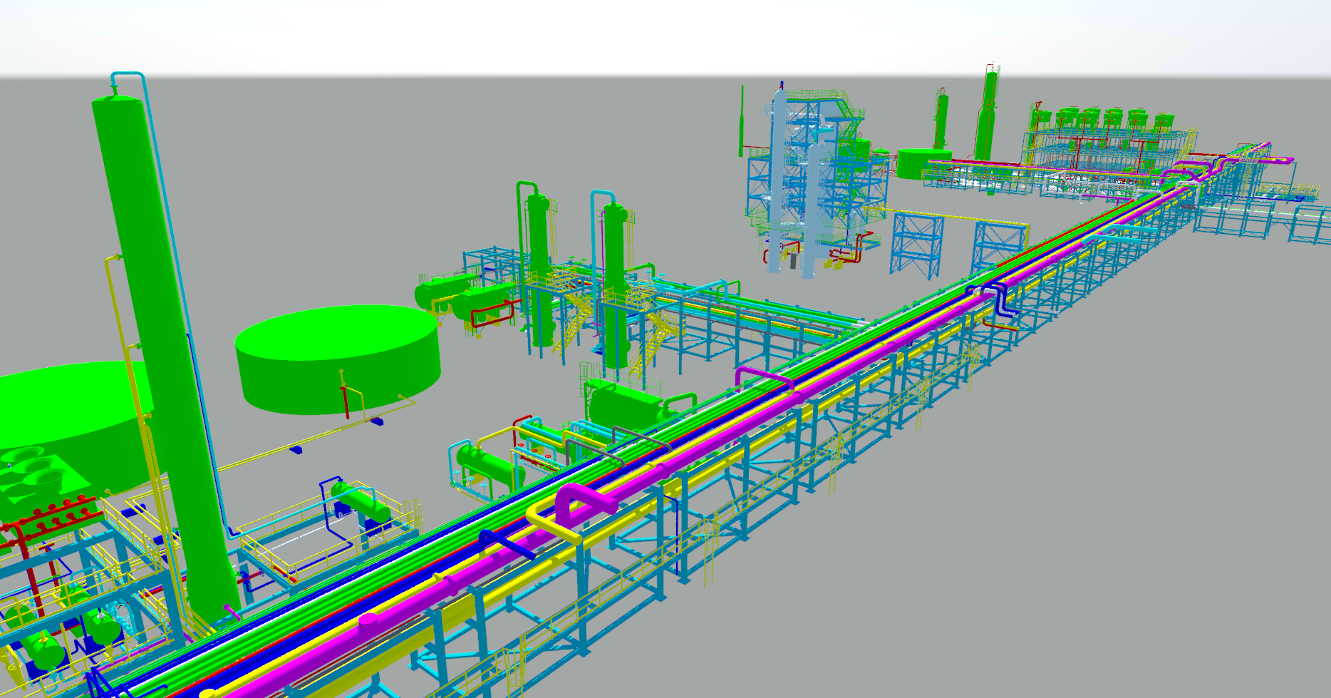
Plant 3D – Piping layout & isometrics
Gas station, process area or pipeline project – Worley / Procure SpA